History
The first oil well was drilled in 1859 in Pennsylvania, but it wasn’t until the late the 1930s and 1940s when oil began to dominate the US economy.8 The environmental impact of oil drilling was apparent in Pennsylvania and East Texas during the first explorations. However, it was accepted that this was the price to pay to move from an agrarian economy to one that is industrial. Unfortunately, in the south, the effects on rural poverty and land degradation were ignored by the greed of the wealthy.9
In the late 1890s, Arrhenius understood the critical impact of the temperature rise at the Earth Surface with carbon dioxide concentration.10 Arrhenius calculated an increase in temperature of 8-9 degrees Celsius at the Earth surface in the Arctic region would occur with an increase of carbon dioxide of 2.5-3 times that amount at his time, about 295 ppm.11 In 1960, Keeling had recognized the need to quantitate the changes in carbon dioxide concentrations by building an experimental station in Hawaii.12,13 The Intergovernmental Panel on Climate Change (IPCC) was created in 1988 to bring scientists from all United Nations member countries to create a nonjudgmental environment to bring knowledge and create ways to mitigate the impact of climate change.14 In 2006, our former Vice-President wrote a book to enlighten Americans about the challenges ahead due to global warming.15 There are still challenges today for Americans to understand the impact of climate change.16,17 In spite of the resistance to the acceptance carbon dioxide heating our plant, the greatest increase in world energy usage is in renewables (~4x) followed by natural gas (~2.5x) and then petroleum (~2x), while nuclear and coal sources of consumption decrease.18
Environmental Impact
Figure 1A illustrates graphically the measurements made of the carbon dioxide concentration in the air and the melting of the Arctic ice in terms of surface area using the data referenced herein.19,20 NASA shows an average 12.8 percent decline in average September sea ice since the 1990s. Visually, pictures taken from space show one million square miles of the Arctic Ocean ice (the size of California, Indiana and Texas combined) has melted in the last 50 years; the icecap has reduced to half its size.21 Alaska, Canada and Greenland have experienced a 7 degree Fahrenheit increase in temperature in the last 50 years. Polar bears are becoming extinct and the ecosystem is changing. The frozen tundra is turning into temperate forests. Greenland once a frozen mass is seeing a farming boom of broccoli and potatoes. Countries such as Russia, Canada, and Norway, whose boundaries were defined by land and ice are becoming territories whose borders include open-ocean and the natural resources in these waters are under discussion in the United Nations. The melting of the ice reveals fossil fuels, natural gas, gold, lead, magnesium, and zinc in significant amounts. New sea routes are opening that are as much as 25% shorter than some routes critical to shipping of oil through narrow straits. The climate change observed is large enough to change the economic powers that exist today.22 The driving force to develop renewable energy is not about running out of fossils fuels; it is about the cost of drilling, securing delivery and saving our planet.23
Figure 1B illustrates a proportional increase in world energy consumption with world population graphed using the data referenced herein.24,25,26 Since 1920, there have been 3 components to global growth. One is the increase in world population.27,28 Two is an increase in economic growth with an increase in industrialization.29 Three is an increase in the carbon footprint, the amount of carbon dioxide in the air.30 With respect to population, the current world population is 7.6 billion.31 It is predicted by the U.S. Census that China and India will reach a population of 1.43 billion and 1.28 billion people, respectively. The United States is the 3rd most populated country at 323 million people.32 The U.S. Census projects a maximum world population of 10 billion in 2050, where after it will decline. The population will start to decline in 2030 and 2050 for China and India, respectively. Population changes in Africa, parts of South America and the Philippines are hard to predict.
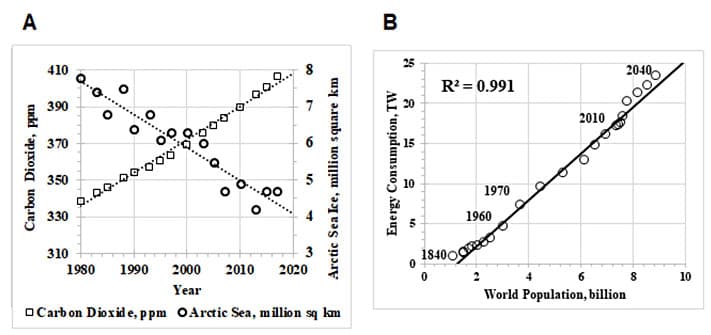
Figure 1. Impact of Industrialization. A) Atmospheric Carbon Dioxide Increasing and Arctic Ice Decreasing in the last 40 years. B) Global Energy Consumption increases Proportionate to World Population.19,20,24-26
Economic Stability
It is said that Energy, not the dollar will be the currency of the world.33 In order to maintain a stable and sustainable, economic global supply of energy, it is critical to reduce the carbon dioxide footprint and secure the supply chain by avoiding civil unrest.34,35 Safeguarding maritime choke points (e.g. the Strait of Hormuz, Strait of Mandeb, Strait of Malacca, Panama Canal, Suez Canal in order of significance) where 61% of the world’s oil trade operates via the sea routes is critical to avoiding a world energy shortage and crisis.36,37 A summary of the complex international political dynamics are discussed as they show the magnitude of the challenges of oil shipping security.38,39,40 The political challenges today will undergo a shift and the countries holding economic powers today are likely to change.41,42,43 The rate of development in countries like China, India and Africa indicate that these countries will be our next world powers.
Figure 2A illustrates the financial investment in renewable energy is significant on a global scale (black columns). China has the largest investment and the greater per cent of the total world investment (dotted columns). This is because China has created policies to use green energy such as solar panels and wind energy in a business to make and sell electric cars. China has been caught in the geopolitics of unstable governments for fossil fuels (e.g. Venezuela) and the limitations set for nuclear energy usage. Thus, China is making a strategic move to be a leader in green energy to develop energy and economic independence.44 Europe has invested in renewable energy to reduce the impact of political instabilities in the Ukraine. With this investment and growth, the cost of renewable energy is reducing. On a global scale, solar and wind energy are the fastest growing renewable sources of energy and represent 80% of the renewable energy growth. Nuclear energy use is decreasing with safety risks and hazardous waste management demands while hydroelectric energy is holding constant.45,46,47,48
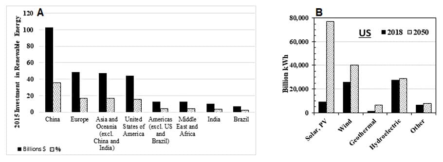
Figure 2. Projection of Renewable Energy Growth A) Investment in Renewable Energy by Country and B) Growth in Energy Consumption by Renewable Energy Source.44,49
Figure 2B illustrates the growth in the United States.49 By 2020, China, U.S. and India will account for 2/3rds of the global renewable energy growth. Integrating the electricity generated from renewable energy in the grid is another challenge. By 2022, Denmark is projected to be the world leader, with 70% of its electricity generation coming from renewable sources next to Ireland (33%), Spain (25%), Germany (25%), England (25%), Italy (15%), Australia (11%), Brazil (10%), U.S.A. (10%), China (8%), India (7%) and Japan (5%).50
Investment in education to support technology growth has been quantified. In 2017, in the STEM areas, China and India graduated 4.7 million and 2.6 million students, respectively, the U.S. graduated 568,000.51 Education is another way to maintain a technology advantage. The number of STEM graduates in 2014 was 1.1 million and 800,000 in China and India, respectively; this shows significant growth of STEM graduates that is explained by the growth in population.52 In the 2016-2017 academic year, the U.S. imported 128,000 and 105,000 students from China and India, respectively, for programs in science, technology, engineering and mathematics.53 Now that Europe and Asia has recovered from the World War, the model is shifting from students staying in the U.S. to students returning to their countries.54
Cost
In Los Angeles, CA, a solar-battery electricity station is being build providing 7% of the city’s electricity in 2023 with cost estimates of 1.997 cents per kilowatt hour (kWh) for the solar power and 1.3 cents per kWh for the battery storage. This is less expensive than any power generated by fossil fuels.55 In Lamar, CO, a 161 MW wind farm was built and the wholesale electricity rate was priced at 2.5 cents to 3.5 cents per kWh. The 2005 gas prices have resulted in fuel costs of 5 cents to 6 cents per kWh.56 In Europe, studies have been done on the cost of combined renewable energy, solar and wind, and compared that with the cost of combined coal and gas power plants. Conventional coal power plants costs are 55 Euro/MWh and 110 Euro/MWh for gas turbine power plants at a carbon footprint cost of 20e/ton. At a carbon cost of 100 Euro/ton, coal power costs 115 Euro/MWh and gas power costs of 155 Euro/MWh. By 2050, it is modelled that the cost of a combined solar/wind power system to give a cost of electricity with low investment costs 80 Euro/MWh and in extreme cases of high investment costs 130 Euro/MWh.57
Concept
Energy is difficult to define and has many interpretations. One thing we know is there are 5 ways energy is generated or transformed: electrical, heat, work, light and chemical bonds. In a wind turbine, mechanical energy (work) is turned into electric energy. In the building of a wind turbine, electrical energy is being generated and measured. In this unit, energy is illustrated by the ability to design and build a machine to create electricity or to light a bulb or to move an object. In order to generate electrical energy, it is required to learn about magnets, electrons and copper wire. Specifically, we will be learning about how magnets in the presence of an insulated copper wire move electrons to generate electricity, one form of energy.
Magnetic Fields
One property of a magnet is that it gives off a magnetic field. For example, we cannot see oxygen with our naked eye, but we can do experiments that demonstrate oxygen exists. The same is with a magnetic field. Let’s imagine a magnet in the shape of a solid rectangular box. If we gather small iron filings and scatter them about a magnet, the filings will align themselves to show a magnetic field, Figure 3A. The magnetic field is a reflection of the net charge accumulating from the alignment of the electrons. We know that the flow of electricity or the movement of electrons is what creates the poles, the magnetic fields and this unique physical property of polarity in magnets. The next question is, what creates the current in the magnet to give off a magnetic field? Inside a magnet there are atoms and these atoms have negative charges called electrons and positive charges called protons. The protons are held deep in the atom; they cannot move. However, the electrons have freedom to move under certain conditions. The electrons move and create electric currents. The current creates magnetic fields. For most materials, the magnetic fields point in many directions and they don’t add up to give a net charge; they neutralize each other. This is not the case for permanent magnets. This is also what happens when an electromagnet is activated.
A magnet is a special type of material. We also know magnetic materials contain a metal and metals contain electrons, some which move readily when a force is applied and other materials where the electron holds tight to the atom. When looking at Figure 3A, let’s say where the fields all come to a point, that point is called a pole. Since the direction of the electron movement is opposite one pole is called North (N) and the other South (S). What is a property of a magnetic pole? If we have two magnets and we try to put the North poles together, the two magnets will repel each other. If we put the North and South poles together, the metals will attract and it will take some force to separate the two magnets, Figure 3B.
There are 3 types of magnets: naturally occurring permanent magnets, temporary magnets and electromagnets. The naturally occurring permanent magnets can be made out of iron, actually an iron composite called ferrite. There is an additional magnet called alnico, which is made of aluminum, nickel and cobalt as well as trace amounts of other elements. Another type of permanent magnet is made out of a composite of elements neodymium, iron and boron. This is called a rare earth magnet. These magnets are inexpensive and will be used in our class. Lastly, another natural rare earth magnet that is quite powerful is made out of samarium and cobalt.
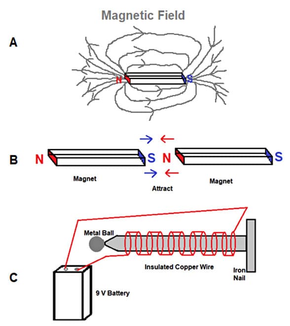
Figure 3. Illustrations of Magnets. A) Magnet illustrating magnetic fields not seeing by the naked eye, B) Attractive force exhibited by 2 magnets C) Illustration of Electromagnet.
Temporary Magnet
A temporary magnet is made, for example, by rubbing a nail or iron with one pole of a permanent magnet. The amount of magnetic force increases with each stroke. With each stroke, the electrons inside the iron are aligning. For a short period of time, the iron will have a North and South Pole. Weak magnets can be made to pick up items like a paperclip.
Electromagnet
An electromagnet is artificially created by using a battery to run current through an insulated wire wrapped tightly around an iron core, such as a nail, Figure 3C. The iron piece will have a North and South Pole and it will pick up metallic objects such as a metal ball or a paperclip. In order to magnetize the nail, the 9 V battery is used to run a current through the copper wire and the flow of electrons (current) in the presence of iron creates the magnetic effect. Once the battery is disconnected, there is no magnetic force and thus no magnet.
Electricity and Energy
The movement of electrons through, for example, copper wire is current and current is used to make electricity. Copper has the unique property that it has an electron that it is ready to give up, allowing an electron to leave the house to run in the magnetic field. In the presence of a magnetic field, the electron in copper that is furthest away of the center of the atom will give off an electron and this electron will move in the direction of the electric field, Figure 4A. The movement of electrons is called current and this it is how electricity is created. The electrons are shown in purple dots, the copper atom is shown in the center and the copper atom that has given up its election is called a copper ion. Figure 4A illustrates copper atoms with electrons rotating in the paths farthest away from the center of the atoms. In the rotation furthest from the center, it is like the electron has nobody to play with, so it bumps into its friends in the magnetic field and as they bump, the energy flows (e.g. like a ripple when a rock is thrown in water). The magnetic field is shown with grey lines. Figure 4B illustrates a fun exercise to do with the students. Here, the negative pole of a battery is set on a round magnet and copper wire (no insulation) is rolled around the battery. The electric and magnetic fields twirl the copper wire. The copper wire is shown in red. By attaching a voltmeter on each end of the copper wire, the current is measured.
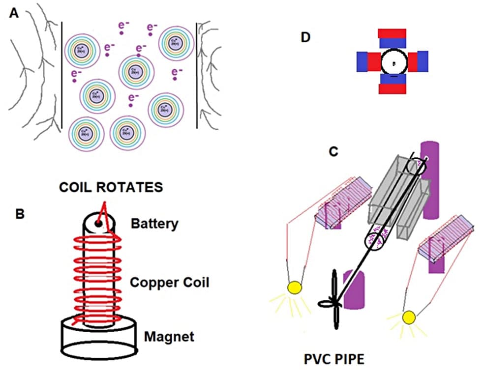
Figure 4. A) Diagram of Copper, Cu+ and free Electrons, B) Diagram for Rotation of Coil, C) Diagram of a Generator Design using PVC Pipe, D) Illustration of the Poles of the magnet direction for 4C.
Figure 4C illustrates a generator made from 1” OD PVC pipe (purple). This has become the preferred design due to the many ways efficiency can be improved and the design can be scaled. First, several tightly bound bundles of copper coated wires (red lines) are coiled on a non-rotating plate called a stator (blue). This stator is made of 2 pieces of 2.5”x3/4” iron strip and folded to give some thickness 1/8-1/4”. The magnets (grey) are attached to each side of the PVC pipe with glue. The magnets must be placed around the PVC with opposite poles adjacent to the pipe as shown in 4D. A nail is held in place in the PVC pipe by wrapping it with tape until it holds by friction and a turbine is attached to the nail. When the turbine turns, so do the magnets. In the presence of the stator windings, a magnetic field is created enabling electrons to light a hobby bulb. This design can be scaled for industrial usage. For example, the number of stator coils can be increased as can the number of magnets. The management of the winding of the coils can enable a significantly greater generation of electricity. Hoover Dam uses this type of design to take water flow and rotate a turbine using a similar generator design.
Fundamentals of Wind Turbines
The familiar term of Windmills is common. A windmill uses mechanical energy to move materials such as water. Wind turbines are used to take mechanical energy and create electrical energy.
Wind turbine blades are shaped similar to an airplane wing. The principles of what make an airplane fly and how the blades turn are the same. On one side of the blade, the blade is curved so a pocket of air is made by the high velocity of the wind passing over it. This provides “lift” and enables the blade to turn. The rotation of the shaft attached to the turbine is passed through a magnetic field created by magnets. The magnetic field moves the electrons inside the copper and mechanical energy is converted to electrical energy; this is called a generator. Our houses run at 110 V and 60 hertz. Depending on the type of generator, the passage of electrons will have to be managed using electrical tools to meet the needs of the grid or our appliances. From here the electricity can be stored in a battery or consumed as it is generated.58 In the classroom, turbine blades can be made out of 8” diameter of thin PVC piping and cut to make the shape of an airplane wing. Each blade is attached to a flat plate. The flat plate is attached to a shaft. As in Figure 4A, the shaft turns the magnets and the coils produce current that is converted to electricity.
It is likely intuitive that the faster the wind speed, the faster the rotor turns and more electricity is generated. Note, if a rotor turns too fast, the mechanical strength of the blades may be surpassed or the generator may burn out due to too many electrons that are traveling through the wire. On a commercial wind turbine, between the rotor and the generator, a set of gears are put in place between the shaft of the rotor and the shaft of the generator to maintain an electric current that is appropriate for the generator. When the rotor rotates too fast, a break is applied to slow it down. How does the brake “know” when it is to be applied? An anemometer is placed on the casing of the wind turbine, called the nacelle. The anemometer measures wind speed. The anemometer sends a signal to the control box of the brake to keep the blades at a constant speed of rotation.
Another aspect of wind turbines is how high above the ground does the turbine need to be mounted? The wind speed increases the further up from the Earth’s surface. Tower heights vary from 100 to 160 feet depending on the length of the shaft and the area the rotor traverses.59
Simplifying a Wind Turbine
There are two types of windmills, vertical and horizontal. Due to shorter lifetimes in the field, failed vertical windmills were replaced with horizontal windmills.60 A windmill takes mechanical movement and converts it into electricity; this is called a generator. This is the opposite of a motor, which takes energy and creates mechanical movement. Many of the components of a motor and a generator are the same. A prototype with main components is illustrated in Figure 5(1). Wind causes the rotor (A+B) to turn. The rotor turns 2 magnets (D) glued to the nail (C) where a spacer of glue (K) and cardboard (E) keeps the magnetic bars parallel to each other. The two magnets are placed across the nail in the direction of attracting each other. Note that the 4 sided cardboard box is not attached to the nail nor to the magnets, thus washers (G) will stabilize the nail. Actually, the box is made first and the nail is pierced into the cardboard. The magnets are attached inside the box. The insulated copper wire (F) is wrapped tightly around the box (E) with one set of windings on one side of the nail and a second set of winding on the other side of the nail. The insulation on the two copper wire ends is removed and attached to the bulb (J) and then a voltmeter (I). It is possible to purchase the generator. The concept of how a generator works and removing the “magic” surrounding how a generator works is fundamental to understanding how a magnetic field generates an electric current in copper wires.61,62 The silver magnets (D) are inside the cardboard. Smaller magnets are stacked in this figure. The red insulated copper wire is seen wrapped around the magnet.
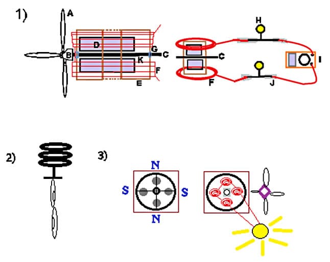
Figure 5. Diagram of Class Prototype Wind Turbine. (1) First Generation Low Cost Wind Turbine Generator, (2) Temporary Magnetism, (3) An Alternative Design to Figure 5(1) and Figure 4(C) for electricity generation in a Wind Turbine.
For demonstration purposes, a handle was put on the generator, instead of turbines. The excluded assemblies from this wind turbine prototype is the gear box, the brake, the anemometer, the yaw (pitch system) and the tower. This prototype was made for the Yale National Initiative summer 2019 meeting; however, the safety hazard of putting the hot glue on the magnets inside the box initiated a redesign.
Figure 5(2) is an illustration of temporary magnetism where 3 circular magnets are attached, temporarily magnetizing a nail and then paper clips. Figure 5(3) is an illustration of another generator design similar to 4C. In this design, 1 or both CDs are glued to a rigid cardboard piece. Then 4 circular neodymium magnets are glued to the CD where the opposite poles of each adjacent magnet face the CD. A washer and a short bolt are glued to the CD. Then a bobbin is used as a set of ball bearings so the top CD turns. Then 4 windings are made each with 250 wraps. These are glued to the CD connected with one wire. A washer is glued to the center of 2nd CD. The second CD in inserted through a bolt and nut with blades attached. Turn the blades and the light will turn on. Instead of a light bulb, a voltmeter can be attached to measure the current.
Comments: