Heart Function
The heart is a remarkable organ that pumps from 5 to 30 liters of blood per minute. It is roughly the size of a fist and pumps two-thirds of its contents, approximately 70mL of blood, upon each contraction, which occur 60 to 80 times per minute. The heart must continue this pace without fail for millions of contractions a year for potentially a hundred years or more. On average the heart pumps 4800 liters of blood throughout the body each day. How does it do it?
My unit will focus on the mechanics of heart function. First, we will explore the parameters that the heart must meet. This includes the differential heart pressure, called the pulse pressure, which in healthy adults is around 40 mm Hg (this is the differential between 120 mm Hg systolic pressure over 80 mm Hg diastolic pressure). This pressure drives the blood through the vessels of the cardiovascular system. This pressure is necessary to create a flow, which is generated against the resistance to flow provided by the blood vessel network. Therefore, the unit will also address the resistance of the arteries, capillaries and veins, particularly the arterioles where muscular activity controls the diameter of opening. Vessel diameter is the chief factor in vessel resistance to flow, which the resistance R varies as radius, r, to the fourth power, r 4! In completing this unit, students will experiment with the fact that the cross sectional surface area of fluid in the capillaries is large and, as a result, the blood velocity in the capillaries is slow, allowing sufficient residence time in the capillaries for diffusion. All of this will be devoted to getting the students to have a sufficient appreciation of the parameters of the heart to create and to design a single pump heart that will behave in a similar way to a real heart with a simulated circulation system.
Purpose of the Heart
The purpose of the heart is to circulate nutrients, oxygen, and other chemicals to all cells in the body and to carry waste away from the cells. Our blood is a remarkable fluid that makes all of this possible. It is the job of the heart to act as a pump to move the blood throughout the body. The heart pumps at a rate that ensures that a blood flow sufficient to satisfy the requirements of the cells is achieved. The circulatory system carries the blood from the heart to the cells and back.
The circulatory system is made up of vessels of varying size. Vessels carrying blood away from the heart are called arteries. The smallest vessels, where most transport of nutrients occurs, are called capillaries. Vessels that carry blood back from the capillaries to the heart are called veins. The circulatory system provides mechanisms for regional control of blood flow, so that blood goes where it is needed at any given moment in time. This control is provided primarily by changes in diameter of small arteries known as arterioles. Because the whole network of blood vessels displays resistance to flow, the blood must leave the heart at a high pressure and return at very low pressure.
Circulatory System Analogous to Electrical Circuit
A strong correlation can be made between the flow of fluid through a cylindrical tube and the flow current through a simple electrical resistor. Fluid flowrate is related to pressure drop by the following equation: ΔP= QR ,where ΔP is the pressure drop from tube inlet to outlet, Q is the volumetric flowrate of fluid, and R is resistance. This is an equivalent equation to Ohm's Law: ΔV=IR, where ΔV is electric potential difference or voltage, I is electrical current and R is electrical resistance. So ΔP=(P o-P i)= RQ where R=8µL/Πr 4, where Μ is viscosity, L is length and r is the radius of the vessel. Therefore, pressure-flow behavior in the circulatory system can be equated to voltage-current behavior in a simple resistive electrical circuit. In addition, the resistance to flow in a simple cylindrical vessel can be estimated from the geometry of the vessel—its radius r and length L—and the viscosity of the fluid flowing through it.
Heart Anatomy
The heart is composed of four chambers. There is a right side and a left side, with two chambers each. The two chambers on each side are an atrium and a ventricle. The left side of the heart is larger and pumps oxygenated blood to the entire body. The right side of the heart pumps deoxygenated blood to the lungs, where it is oxygenated.
Oxygenation in the lungs is accomplished by flowing blood through an immense array of capillaries (the smallest vessels that are so small that they may only allow red blood cells to travel through single file!) in close proximity to lung air, which is possible because of the tremendous surface area of the lung. Although the lung's volume is only about a liter, the surface area is approximately the size of a tennis court as a result of the fractal bifurcation (branching into two) of the lung into 2 2 3 nearly spherical alveoli (the smallest unit of the lung)! Diffusion is the passive process of transport from high concentration to low concentration. The blood flowing into the lungs is deoxygenated; it has relatively high concentrations of carbon dioxide and low concentrations of oxygen. The blood utilizes a compound in red blood cells called hemoglobin as the component that greatly increases the solubility of oxygen, greatly increasing the efficiency of the heart and circulatory system. Upon reaching the lung, blood exchanges carbon dioxide and oxygen, there by becoming "oxygenated". The blood is pumped to the lungs at low pressure, since there is low resistance and the lungs are close to the heart
The heart is a double pump with two separate parts. The circulatory system is a closed loop, which can be described by starting at any point, so let's start when the blood comes back from the cells. The deoxygenated blood returns to the heart by the two largest veins called the superior and inferior vena cava. The vena cavae carry the blood into the right atrium at low pressure passively, meaning that there is no valve between the vena cavae and the atrium. When the heart begins to contract, contraction starts in the right atrium, causing blood to flow from the right atrium into the right ventricle, through the tricuspid valve, which prevents back flow. As the heart contraction moves from atrium to ventricle, the pressure in the right ventricle increases until the blood is ejected into pulmonary artery through the pulmonary valve. This blood, ejected from the right ventricle, divides into two paths continuing to one of the two lungs, where it is oxygenated (as described in the paragraph above). The blood returns to the heart in the pulmonary veins which both go into the left atrium. When the left atrium contracts, blood is forced through the bicuspid valve into the left ventricle. Ventricle contraction causes an increase in the blood pressure, because blood is an incompressible liquid, and the volume is decreasing. When the pressure inside the ventricle exceeds the normal blood pressure in the aorta (the artery leaving the left ventricle), the aortic valve opens, ejecting the majority of the blood in the ventricle into the aorta! This blood travels through the arteries, arterioles, capillaries, venules and veins until it reaches the vena cava and begins the circulation again (See Diagram 1 below).
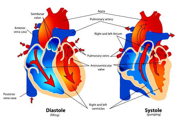
(Diagram 1 - thanks to wpclipart.com- public domain)
The blood flow path to the lung is called the pulmonary circulation and the path to the body is called the systemic circulation. The heart contracts approximately once per second, and each side of the heart beats simultaneously with each contraction. The pathway for electrical excitation is a bit complicated, but it results in the contraction of both atria first then the ventricles in a wonderfully synchronized and efficient pumping motion. The excitation of the heart cells causes a spreading wave of contraction from heart cell to heart cell. Each cell has a delay mechanism of approximately a half-second, before re-excitation is possible, so that the contraction is perfectly synchronized and does not circle back upon itself. The beating heart operates with an amazingly choreographed motion that optimizes the heart's pumping function.
Heart Valves
The valves of the heart are necessary to prevent back flow when the heart contracts. The valves allow blood to flow in only one direction. The valves are open when the pressure behind the valve is higher than the pressure up-stream from the valve. This elevation in pressure occurs when the heart contracts. First the atrium begins to contract, in effect, priming the ventricular pump for maximum stroke volume. The valves are a beautiful design of tissue that is separated into two or three triangular flaps that open when the pressure difference behind them is greater than the pressure in front. The open valve allows fluid to flow, but when the pressure in front of the valve exceeds the pressure behind it, the valve shuts. There are also a myriad of tendon fibers that attach some of the valves to the heart wall.
The natural design of human heart valves is ingenious and difficult to successfully replicate. Biomedical engineers have found ways to use valves from other animals—usually pigs and cows—to replace valves in humans: the animal valves are treated with chemicals to make them inert after implantation. In addition, engineers have made totally synthetic valves from polymers and metals and ceramics, which can function almost as well as natural valves.
The Aorta
The total flow rate from the heart (also called cardiac output) is the stroke volume (or volume of blood ejected on each contraction or beat) times the number of beats per minute. When the left ventricle contracts, blood flows into the aorta. The heart beat results in high pressure in the aorta. The aorta is flexible so that it can expand when the blood is ejecting from the heart. This also results in a "secondary pump" when the aorta rebounds elastically back to its original shape, which helps to maintain a more constant blood pressure between beats.
Biocompatible Materials
An advanced consideration and a primary reason for the limited success so far with artificial heart replacement has to do with biocompatibility. The artificial hearts that we will design are made out of non-living materials. The body's immune system is designed to detect foreign bodies and to attack them in an effort to isolate them and eradicate them if possible. Therefore, it is necessary to fool the body's immune system into not recognizing the implanted material as foreign or to at least limit the body's immune reaction. This is the nature of a biocompatible material. In the projects that students will conduct as I teach this unit, the students will have to consider what their artificial heart prototype could eventually be made of to make it biocompatible. Some metals and some polymers have proven to be a good starting point.
Many students may know or find out that the problem, or danger, with many implanted devices, is clotting. To further explain the body's immune system response, it is important to understand how the body attempts to isolate an implanted material. A simplified explanation is that the body's immune system, upon recognizing a material as foreign, will attempt to isolate the material. It does this by surrounding it, or coating it. This coating is the result of a complex set of reactions within the body, and it is related to the body's attempt to heal a wound. The immune system forms fibrous "clots" that in the case of the wound seal the "hole" while in the case of the foreign material attempt to encapsulate it.
Clotting on a biomaterial is dangerous because of the risk that a piece of a clot will break free and travel through the circulatory system. If this happened, the embolized clot can block smaller blood vessels down-stream. This is potentially deadly. If it occurs in the brain, the embolism can cause a stroke and in the lung an embolism can prevent a region of blood flow from collecting oxygen. Clotting is particularly problematic with implanted devices because the foreign material causes a large scale clotting that then poses a very high risk of the clots breaking free. My students will have to consider the biocompatibility of the materials from which they would construct their optimized prototype. Another issue that must be researched and addressed is the concern of having a foreign material contract to simulate a beating heart and whether this poses more danger of throwing clots.
The Physics of the Heart
There are a wide range of physics concepts involved in constructing an artificial heart. Here I will consider the Mechanics of constructing a heart and the biomedical considerations. The designs of the students will inevitably dictate the teacher of creative design to expound on additional physics concepts.
Mechanical Principals of an Artificial Pump
The first challenge for the students is to design a "beating" or reciprocating heart pump. How can this be done? Most pumps are propellers powered by a motor. However, these propellers do not simulate an actual heart, they are not the simplest solution, and they are known to cause problems with clotting. So I would like my students to explore the most direct methods that will simulate a "contracting" heart. To do this, we must first consider the Mechanics involved in this type of motion and the physics that can help to guide this exploration.
Simple Machines
My students will have to utilize simple machines to design and create solutions for a moving artificial heart. Simple machines are broken down into two families, levers and inclined planes. Levers include simple levers, wheel and axle, and pulleys. Inclined planes include the simple inclined plane, the screw, and the double inclined plane the wedge. It is not necessary for my students to know which type of simple machine they are using or which class of simple machine they are creating; however, a basic knowledge of simple machines will provide my students with more tools to address how to create different types of motions, such as up and down, circular, and at an angle. With an understanding of simple machines, they can begin to combine them into a complex machine. Students will determine the mechanical advantage of utilizing various simple machines and how to combine them for the desired effect.
Mechanical Advantage
Mechanical advantage (MA) is the proportional increase or decrease in the output force related to the input force. An MA of 1 means that a simple machine provides no increase in the output force. An example of this is a seesaw (which is a lever) where the pivot is in the middle. The input and output forces are the same so MA=F o u t p u t/F i n p u t = 1. A lever involves the use of a pivot and the MA can be calculated by the relationship of the length of the lever on the side of the input force relative to the size of the remaining lever on the output force. So if the pivot is two-thirds down the lever away from the input force, then the proportion would be 2/1 = MA of 2. This means that the output force would be twice as great as the input force. This concept will be useful to the students in the design of their complex machine that make up their artificial hearts. Now we know that, in physics, you cannot get something for nothing (because of conservation of energy) so what is the consequence of having a mechanical advantage? The output force in our last example doubled. This is achieved by the input distance increasing by the same proportion. So the input distance is double the output distance (I must move the lever twice as far when the MA is 2 to produce double the force which acts over half the distance!). This is a crucial concept in design utilizing machines.
I have used the example of the lever, but the same concept of mechanical advantage applies to all simple machines, whether it is an inclined plane or a wheel and axle. Usually we think in terms of MA's over one so that we are increasing the output force, however, there are situations in which the MA will be less than one, where the intention is to decrease the input distance instead. Disregarding friction (which may not be possible in real world designs), the input force times input distance = output force times output distance. Manipulating this simple equation will be essential in our design of a heart.
Motors
Motors convert electrical energy into the rotational motion of a shaft or axle. They do this by utilizing the physical principal that moving electricity produces a magnetic field and vice versa. Consequently, by supplying current (moving electricity) in a magnetic field a force will be generated. A motor is an application of this principal. A magnet coiled with wire that is able to pivot around its center while receiving current experiences a force that causes the assembly to rotate. This is the basis of the motor.
It is likely that motors will be a central element of the students' artificial hearts. Some of the key concepts necessary to utilize motors are revolutions per minute (RPM) and torque. The RPM of a motor rates the speed that the motor will spin. The torque provided by the motor is an indication of how much force the shaft of the motor can supply. These parameters are often inversely proportional so the students will have to understand what kind of motor they will need. Most likely, the students will need low speed, high torque motors, but most motors are high speed, low torque. Therefore, the students will need to understand how to use gears to convert speed and torque. Gears utilize the concept of MA to convert the motion of the motor into the desired output. Usually motors are geared down. This means that a high number of rotations (RPM's) of the motor at low torque are converted into a low number of rotations (RPM's) at proportionally higher torque. There are a variety of different types of gears that may be required if the students are not able to have access to the type of motor that they require and must make adjustments.
Advanced Biomedical Considerations
Students will need to solve a variety of problems to create a mechanical model simulating the heart. First, they will need to design a pump. Eventually, the students will be able to consider how to solve other issues such as: how to get a valve to work; how to limit flow disturbances that lead to clotting; how to maintain a constant pressure once the pumping is achieved; how to use compliant tubing to mitigate fluctuations in pressure; how to balance output and return in a closed circuit; how to control the flow to different areas of the body; and how the pump will be powered.
These are some of the concerns that students may address once they have created a functional pump. Each individual group will build a prototype of a beating heart and will determine which additional aspects to explore. Each area is rich enough to justify the groups to differentiate into sub groups that will explore various aspects or systems of the project. This will be determined by the time required to create the heart pump.
Each team will design a functional pump. The cardiovascular system (that is, the flow circuit that the pump must serve) will be presented to the students as a series of vessels decreasing in size dramatically, but paradoxically increasing in volume from arteries to arterioles to capillaries because of branching. The artery can be simulated as a single large vessel that connects to the capillary bed for the purposes of testing our pump. The capillary bed can be reduced to a large container of fluid, which simulates the large cross sectional area of fluid in the capillaries. The veins leading back to the heart can be simplified to a single large vein, one of the vena cava, which exits the "capillary bed" container and returns to the artificial heart pump. This representative "circulatory system" can be utilized to test the artificial heart pumps. If this "cardiovascular system" were expanded, it would entail a forking system of vessels that decrease in diameter and likely would have hose clamps on the "arterioles" that would enable for the control of resistance and pressure and a variable output to different parts of the system. In our circulatory system the vessels will be clear and the "blood" fluid (water) will have some particulate (likely glitter) floating in it so that the rate of flow can be seen and measured.
As a preliminary exploration, a pumpless "circulatory system" can be built that relies on gravity for the pressure. This beginning "heart" will consist of a container with a hole in it raised a certain height to create a desired pressure and flow rate (the pressure drop generated by a column of water of height h is equal to: ΔP = dgh, where d is the density of water and g is the acceleration due to gravity. This reservoir will be attached to the "circulatory system" of clear vessels and allowed to drain into another container that rests on the ground. The primary task for creating the artificial heart will be to address and solve how to get the "blood" back up into the top container. Initially the size of the pumps designed by the students will not be a consideration. Eventually, as the work proceeds, the students will be asked how they would optimize their design so that the pump could be able to be inserted in the chest of a recipient.
In my two second year physics classes (AP Physics B), for which this unit is intended, we will utilize this unit to lead into the correlative concepts of fluid flow rates, Bernoulli's equation, hydrostatic pressure, surface tension, cohesion and capillary action as they relate to laminar flow and resistance in vessels. We will consider the pressure exerted on parts of the mechanical pump system by the incompressible liquid once we have explored hydraulic pumps and the relationship of pressure to area. I also envision this unit as a capstone project for first year physics students once they have completed their study of Mechanics.
Student Demographics
My high school has approximately 1350 students with 400 of them being designated as gifted. The school is roughly 55% Caucasian and 36% African American and 9% other. There is a range of socioeconomic backgrounds as well, with approximately 35% of the students receiving free or reduced lunch. However, all students are required to take physics and all juniors are encouraged to consider taking a second year of physics. My Physics AP B is a second year algebra based physics course. There are 50 students taking the class. In addition, in our school 20 students are taking calculus based AP Physics C and 20 are taking advanced AP C Mechanics and Electricity and Magnetism. My AP Physics B classes are fairly representative of the school population.
Comments: